
A level-to-pulse converter produces a single cycle pulse each time its input goes high. It’s a synchronous rising-edge detector. Sample uses:– Buttons and switches pressed by humans for arbitrary periods of time – Single-cycle enable signals for counters.
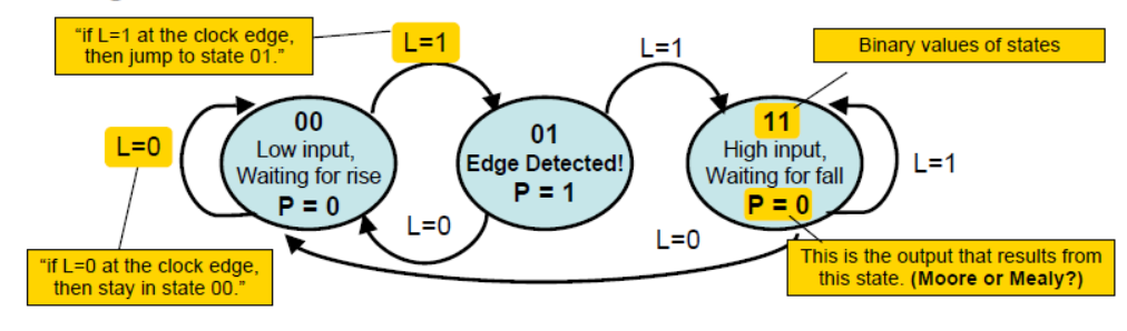
Type[1] >> This is the moore fsm for the level to pulse design.State transition diagram is a useful FSM representation and Transition diagram is readily converted to a state transition table (just a truth table).

Combinational logic may be derived using Karnaugh maps
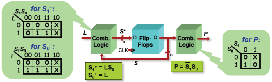
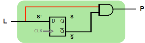
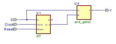
Moore FSM circuit implementation of level-to-pulse converter:

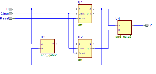
code is given below for moore fsm

library IEEE;

use IEEE.std_logic_1164.all;

entity moore_LTP_fsm1 is

port (

clk: in STD_LOGIC;

L: in STD_LOGIC;

rst: in STD_LOGIC;

P: out STD_LOGIC);

end moore_LTP_fsm1;

architecture moore_LTP_fsm1_arch of moore_LTP_fsm1 is

-- SYMBOLIC ENCODED state machine: Sreg0

type Sreg0_type is (

S1, S2, S3

);

-- attribute enum_encoding of Sreg0_type: type is ... -- enum_encoding attribute is not supported for symbolic encoding

signal Sreg0, NextState_Sreg0: Sreg0_type;

-- Declarations of pre-registered internal signals

signal int_P, next_P: STD_LOGIC;

begin

-- concurrent signals assignments

-- Diagram ACTION

----------------------------------------------------------------------

-- Machine: Sreg0

----------------------------------------------------------------------

------------------------------------

-- Next State Logic (combinatorial)

------------------------------------

Sreg0_NextState: process (int_P, L, Sreg0)

begin

NextState_Sreg0 <= Sreg0;

-- Set default values for outputs and signals

next_P <= int_P;

case Sreg0 is

when S1 =>

next_P <= '0';

if L='1' then

NextState_Sreg0 <= S2;

elsif L='0' then

NextState_Sreg0 <= S1;

end if;

when S2 =>

next_P <= '1';

if L='0' then

NextState_Sreg0 <= S1;

elsif L='1' then

NextState_Sreg0 <= S3;

end if;

when S3 =>

next_P <= '0';

if L='0' then

NextState_Sreg0 <= S1;

elsif L='1' then

NextState_Sreg0 <= S3;

end if;

--vhdl_cover_off

when others =>

null;

--vhdl_cover_on

end case;

end process;

------------------------------------

-- Current State Logic (sequential)

------------------------------------

Sreg0_CurrentState: process (clk)

begin

if clk'event and clk = '1' then

if rst='1' then

Sreg0 <= S1;

else

Sreg0 <= NextState_Sreg0;

end if;

end if;

end process;

------------------------------------

-- Registered Outputs Logic

------------------------------------

Sreg0_RegOutput: process (clk)

begin

if clk'event and clk = '1' then

if rst='1' then

int_P <= '0';

else

int_P <= next_P;

end if;

end if;

end process;

-- Copy temporary signals to target output ports

P <= int_P;

end moore_LTP_fsm1_arch;
Moore circuit with its waveform.

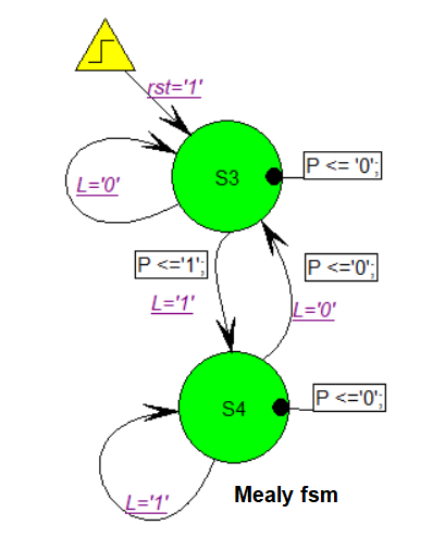
Type [2]>>Design of a Mealy Level-to-Pulse. Since outputs are determined by state and inputs, Mealy FSMs may need fewer states than Moore FSM implementations.
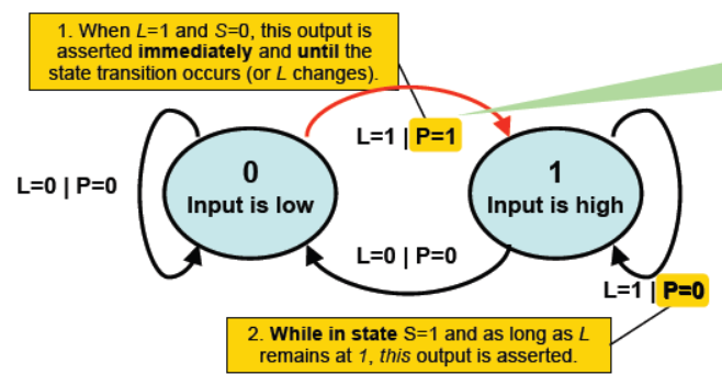
Its state transition table.
FSM’s state simply remembers the previous value of L • Circuit benefits from the Mealy FSM’s implicit single cycle assertion of outputs during state transitions.
library IEEE;

use IEEE.std_logic_1164.all;

use IEEE.std_logic_arith.all;

use IEEE.std_logic_unsigned.all;

use IEEE.std_logic_signed.all;

entity mealy_LTP_fsm1 is

port (

clk: in STD_LOGIC;

L: in STD_LOGIC;

rst: in STD_LOGIC;

P: out STD_LOGIC);

end mealy_LTP_fsm1;

architecture mealy_LTP_fsm1_arch of mealy_LTP_fsm1 is

-- SYMBOLIC ENCODED state machine: Sreg0

type Sreg0_type is (

S3, S4

);

-- attribute enum_encoding of Sreg0_type: type is ... -- enum_encoding attribute is not supported for symbolic encoding

signal Sreg0: Sreg0_type;

begin

-- concurrent signals assignments

-- Diagram ACTION

----------------------------------------------------------------------

-- Machine: Sreg0

----------------------------------------------------------------------

Sreg0_machine: process (clk)

begin

if clk'event and clk = '1' then

if rst='1' then

Sreg0 <= S3;

-- Set default values for outputs, signals and variables

-- ...

P <= '0'; else -- Set default values for outputs, signals and variables -- ... case Sreg0 is when S3 =>

P <= '0';

if L='1' then

Sreg0 <= S4;

P <= '1';

elsif L='0' then

Sreg0 <= S3; end if; when S4 =>

P <= '0';

if L='1' then

Sreg0 <= S4;

elsif L='0' then

Sreg0 <= S3;

P <= '0'; end if; --vhdl_cover_off when others =>

null;

--vhdl_cover_on

end case;

end if;

end if;

end process;

end mealy_LTP_fsm1_arch;
Moore/Mealy Trade-Offs • How are they different? – Moore: outputs = f( state ) only – Mealy outputs = f( state and input ) – Mealy outputs generally occur one cycle earlier than a Moore:
• Compared to a Moore FSM, a Mealy FSM might… – Be more difficult to conceptualize and design – Have fewer states
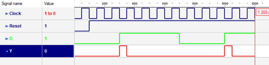

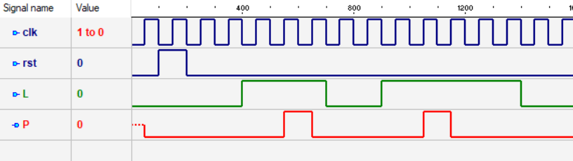
moore fsm and its waveform based on fsm only , seen same result as that of earlier.

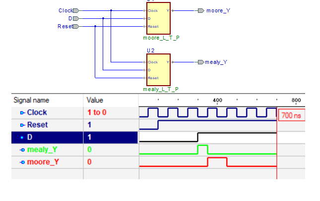
here also mealy fsm and its waveform based on fsm only , seen same result as that of earlier.
let see what will happens after rtl to gate net list transformation using synthesis tool.
Please feel free to drop comment for your quires, codes will be provided on request for free.